
04.12.4 / CDS Training Manual
Screen a pressurized
AS4/3501-6 cylinder.
Recreate the global biaxial load state of a NASA pressure-cylinder program, compare stacking sequences, and define the boundary between laminate screening and detailed fracture analysis.
Complete manuals · download a whole collection
Each collection includes an editable Word manual and its matching searchable PDF, with linked contents, explanatory text, diagrams and references. Theory equations use native Word mathematics. Individual-page PDF buttons remain available.
These are dated reading editions of the public learning content. Interactive studies and account-controlled classroom notes and databases stay online. For current changes, follow the chapter links back to the website.
Current Workbench, reference editions and downloads
Use the online User Guide for current controls, the released model directory for selectable models and compatibility, and the Training Manual for connected exercises. Wider theory references do not mean every formulation is enabled in Workbench.
Dated GUI captures and compiled Web r18 PDF manuals retain their stated scope; they are not a substitute for current hosted Workbench instructions. Find the overview PDF, guides and exercise databases in Your CDS library.
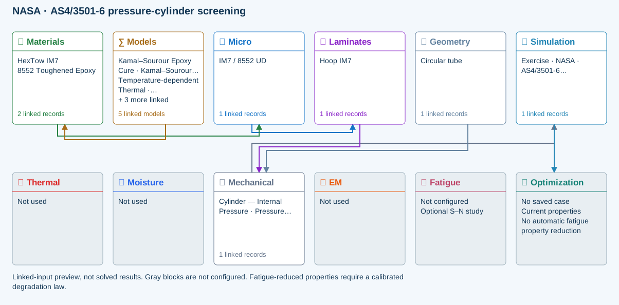
Linked-input preview, not solved results. Gray blocks are not configured.
∑ Selected models & submodels
These are the exercise’s linked choices, not solved results. Open a first-layer model to see its submodels and scope.
Kamal–Sourour autocatalytic · Kamal–Sourour Epoxy Cure
Reusable material model. It contributes only when assigned to a material used by this simulation; separate model records can supply independent properties.
Calibration & applicability
Illustrative model defaults — replace with characterized resin kinetics
Temperature-dependent tabular · Temperature-dependent Thermal
Reusable material model. It contributes only when assigned to a material used by this simulation; separate model records can supply independent properties. Micro uses the 23 °C reference; Process evaluates the same table at local temperature, without extrapolation.
Calibration & applicability
Check source data, applicable environment and validity limits in the model record; saved defaults are not experimental validation.
1D Fickian diffusion · Layered Fickian Diffusion
Reusable material model. It contributes only when assigned to a material used by this simulation; separate model records can supply independent properties.
Calibration & applicability
Check source data, applicable environment and validity limits in the model record; saved defaults are not experimental validation.
Halpin–Tsai · IM7 / 8552 UD
One compatible homogenization model per Micro recipe. Separate recipes compare models; their predictions are not blended.
∑ Theory & assumptionsCLT · Linear thin-wall membrane · Cylinder — Internal Pressure · Pressure vessel
Shared laminate stiffness drives this membrane/CLT path. Failure criteria are independent comparisons, not blended models. Fatigue is a separate assessment.
∑ Theory & assumptionsData travelling between blocks
Micro → Laminates
Predicted ply stiffness, strength, density and expansion properties.
Materials → Micro
Constituent stiffness, strength, density and thermal / moisture properties.
Models → Materials
Model choices and calibrated parameters.
Mechanical → Simulation
SIMULATION selects this case and its analysis model; the case owns its applicable cycle and input references.
Laminates → Mechanical
Ply angles and thicknesses, stiffness, mass and ply properties.
Geometry → Mechanical
Shape and dimensions for the selected structural analysis.
Simulation → Optimization
Linked inputs and current-property response for candidate evaluation.
Reference validation · 2026-09-18
Not benchmark validated
No matched quantitative reference comparison completed for the full exercise.
Recorded baseline only—not a certification of the current database, edited inputs, or every output. Analytical agreement is not experimental material or failure validation.
Source validation, comparisons and tested inputs
Execution: Completed (not validation)
The starter uses IM7/8552, not AS4/3501-6. Supply traceable AS4/3501-6 ply properties, thickness and the source diameter convention before comparison. Slits are intentionally outside this pristine-cylinder model.
- NASA-CR-195101 — Damage Tolerance of Pressurized Graphite/Epoxy Tape Cylinders Under Uniaxial and Biaxial Loading ↗Source study identified; matched slit-cylinder dataset not reproduced. Slit-tip damage and failure pressure are outside pristine membrane scope.
Tested inputs
Input SHA-256: f25f2006b61b91faeeba0759fa4d7a801d98047fe892d401285db11b9d1b9741
Solver source SHA-256: 30c8a614b6cb004a26da8adaf8ab7c534c37c4d534836921939f35a549e1bcc5
- Pristine-cylinder screening only. Slit-tip fracture, splitting, delamination, nonlinear local response and the source’s subcritical damage are not solved here.
Download source-validation evidence (JSON) · Full 104-exercise study
Compare global membrane and first-ply response for two quasi-isotropic AS4/3501-6 stacking sequences under the two-to-one hoop-to-axial loading created by internal pressure.
CDS provides the pristine thin-wall cylinder and laminate-failure screen. The published slit-tip fracture, delamination, subcritical damage and nonlinear local response require a higher-fidelity model.
Published basis
2 primary sourcesReports 305 mm AS4/3501-6 cylinders, 12.7–50.8 mm axial slits, several symmetric stacking sequences, and sensitivity to subcritical damage.
↗NASA-CR-192618Damage Tolerance and Arrest Characteristics of Pressurized Graphite/Epoxy Tape CylindersDocuments quasi-isotropic and anisotropic AS4/3501-6 cylinders pressurized to a two-to-one biaxial far-field stress state.
↗Starting data
Enter in the displayed units| Variable | Value | How it is used |
|---|---|---|
| Material | AS4/3501-6 graphite/epoxy tape | Published cylinder material system |
| Cylinder diameter | 305 mm | Global tube geometry |
| Baseline layup | [90/0/+45/−45]s | Symmetric quasi-isotropic comparison |
| Stacking variant | [0/+45/−45/90]s | Similar in-plane response with different bending coupling |
| Slit lengths in source | 12.7–50.8 mm | Excluded local-damage feature to document |
| Pressure load ratio | Hoop : axial = 2 : 1 | Closed-cylinder far-field membrane loading |
Review checkpoints
Comparison, not certification| Result | Published reference | Interpretation |
|---|---|---|
| Membrane load ratio | Nhoop / Naxial = 2 | Required thin-wall closed-cylinder equilibrium check |
| A-matrix comparison | Nearly equivalent quasi-isotropic in-plane response | Confirms material, thickness and orientation convention |
| D16 and D26 | Stacking-sequence dependent | Relevant to the different damage behavior discussed by NASA |
| Failure-pressure agreement | Not a CDS membrane checkpoint | Requires slit-tip fracture and subcritical-damage modeling |
All exercises, case studies and simulation examples → · Your CDS library: overview, manuals and database downloads →
Create the pristine cylinder baseline
Build the published 305 mm diameter AS4/3501-6 cylinder as an undamaged membrane-screening case.
- Create or select a traceable AS4/3501-6 orthotropic ply record.
- Build the symmetric quasi-isotropic [90/0/+45/−45]s baseline and a duplicate [0/+45/−45/90]s stacking variant.
- Set the circular-tube geometry by inside diameter and laminate-derived wall thickness.
Apply the pressure membrane resultants
For a closed thin-walled cylinder, internal pressure produces a two-to-one hoop-to-axial membrane stress state.
- Enter the internal pressure and verify LiveLoad identifies the hoop and axial directions.
- If entering resultants directly, use Nhoop = p r and Naxial = p r / 2 with consistent units.
- Run a low-pressure case first and confirm strain signs, hoop-to-axial load ratio and laminate orientation.
Screen first-ply and progressive response
Run supported maximum-stress, Hashin or other criteria using documented AS4/3501-6 strength inputs.
- Compare first-ply load factors for the two quasi-isotropic stacking sequences.
- Inspect D16 and D26 and the progressive stress–strain history rather than assuming that equal A-matrices give identical damage response.
- Save each case as a named simulation and compare the result tables.
Identify the required higher-fidelity handoff
Use the CDS result to define loads and material state for a local finite-element or fracture-mechanics model.
- Export the laminate stiffnesses, strengths, pressure resultants and global strains.
- Model the 12.7–50.8 mm axial slit and local mesh outside the current CDS membrane idealization.
- Include nonlinear shell response, delamination and fracture calibration when comparing failure pressure.
- Return validated local-model limits to CDS as documented design constraints rather than hidden correction factors.
Document what the comparison proves
Record the source, exact stack, pressure convention, failure criterion and excluded physics with the saved run.
- Treat the NASA pressure-cylinder results as external validation context.
- Treat CDS output as a pristine-cylinder screening result unless a supported local-damage model is explicitly active.
- Do not claim agreement on slit failure pressure from an unnotched membrane model.
Workbench availability: released models, inputs and compatible study paths. The wider theory library includes reference formulations not available in every Workbench solve.