
Pressure loading produces different hoop and axial demands, and the end condition helps determine that balance. This exercise connects the vessel geometry and loading to the laminate response, then uses layup comparisons to explore how the same membrane demands are carried by different stacks.
Open this exercise in Workbench
Prepare the baseline
Check the radius or diameter convention and whether the ends are closed before running. Keep pressure and geometry unchanged during the ply-balance comparison. Where the exercise supplies membrane relations or published data, use them as a transparent check and document exactly which quantities are being compared.
Worked procedure
1. Inspect the tube dimensions in Geometry and pressure/end conditions in CASES.
2. Run the closed-end vessel; compare hoop and axial membrane resultants.
3. Vary the hoop/axial ply balance and rerun without changing the geometry or pressure.
Review checkpoints
For zero external pressure, closed ends and no additional axial load, hoop resultant is twice the pressure-induced axial resultant.
Verify the wall is sufficiently thin for the selected theory.
Model limits
Thin-wall membrane theory: no through-wall radial stress profile or local end effects.
Interpret the comparison
Keep global membrane behaviour separate from local damage tolerance. If the source discusses slits, cracks or delamination that the selected model does not resolve, document those exclusions rather than inferring their failure pressure from a pristine laminate calculation. Report both the useful global result and the additional analysis needed for the local question.
How information passes between models
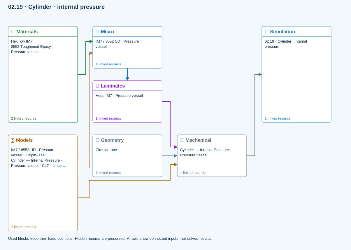
Micro → Laminates: Predicted ply stiffness, strength, density and expansion properties.
Materials → Micro: Constituent stiffness, strength, density and thermal / moisture properties.
Mechanical → Simulation: SIMULATION selects this case and its analysis model; the case owns its applicable cycle and input references.
Laminates → Mechanical: Ply angles and thicknesses, stiffness, mass and ply properties.
Geometry → Mechanical: Part shape and dimensions, thickness or section definition, and model-specific geometric inputs. Each selected case consumes only the dimensions its model supports.
Models → Micro: Applied model assignment: Halpin–Tsai. Model parameters and formulation are used by Micro.
Models → Mechanical: Applied model assignment: CLT · Linear thin-wall membrane. Model parameters and formulation are used by Mechanical.
Further reading and evidence
- Geometry, loading and virtual tests
- Related case study: NASA pressure cylinder
- Run and review a model
- Edit laminate materials, angles and thicknesses
- Apply symmetry and balance
Review the recorded validation scope. Retain the original inputs and solver notices with the results. Representative teaching data are not design allowables.
References and source sections
References are retained with the formulations they support. Software instructions describe implementation scope; a cited source does not establish independent validation of a CDS calculation.