
A bonded joint transfers load through an adhesive layer rather than carrying it uniformly through a single section. This exercise examines the resulting distribution and asks how the chosen geometry and constitutive assumptions influence the reported stresses.
Open this exercise in Workbench
Prepare the baseline
Trace both adherends and the adhesive to their records, then inspect overlap, width and bondline thickness. Establish the baseline before varying the parameter specified in the task. Check whether the selected branch is an analytical approximation or a spatially resolved study, and use only the refinement controls available for that branch.
Worked procedure
1. Trace lower laminate, upper laminate and adhesive selections from Simulation to Geometry.
2. Run and inspect the adherend and adhesive stress/strain fields.
3. Vary overlap or bondline thickness, then refine the available mesh controls to assess peak-stress sensitivity.
Review checkpoints
Check adhesive stiffness inputs and their material assumptions.
Compare field shape and displacement as well as a single peak value.
Model limits
Perfectly bonded linear-elastic interfaces. Mesh-sensitive edge peaks are not joint strength, debonding or damage predictions.
Interpret the comparison
Compare the distribution and peak location as well as the largest stress. Where a mesh is used, establish whether the peak is sensitive to refinement before interpreting it. An elastic stress profile does not by itself predict debond growth or joint strength; those conclusions require the relevant model and calibration.
How information passes between models
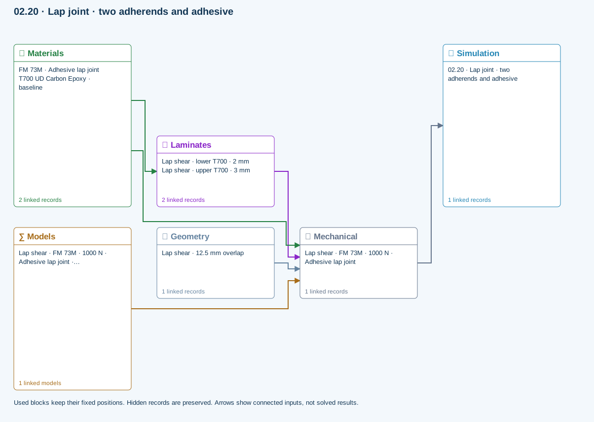
Materials → Laminates: Stored ply stiffness, strength, density and expansion properties.
Mechanical → Simulation: SIMULATION selects this case and its analysis model; the case owns its applicable cycle and input references.
Laminates → Mechanical: Ply angles and thicknesses, stiffness, mass and ply properties.
Materials → Mechanical: Constituent stiffness, strength, density and thermal / moisture properties.
Geometry → Mechanical: Part shape and dimensions, thickness or section definition, and model-specific geometric inputs. Each selected case consumes only the dimensions its model supports.
Models → Mechanical: Applied model assignment: Single-lap x-z plane strain. Model parameters and formulation are used by Mechanical.
Further reading and evidence
- Connect a simulation
- Geometry, loading and virtual tests
- Through-thickness section analysis and assumptions
- Run and review a model
- Connected inputs and result freshness
Review the recorded validation scope. Retain the original inputs and solver notices with the results. Representative teaching data are not design allowables.
References and source sections
References are retained with the formulations they support. Software instructions describe implementation scope; a cited source does not establish independent validation of a CDS calculation.