
Not every laminate needs a micromechanics calculation. This exercise helps you read a stored material or mixed-source stack correctly, tracing each ply back to the properties it actually uses. The distinction matters when historical records, measured properties and calculated Micro recipes appear in the same workspace.
Open this exercise in Workbench
Prepare the baseline
Follow the material reference for each ply and inspect its units, status and source before running. For converted records, distinguish the original data from any teaching loads added during conversion. Establish the baseline response first, then make the comparison specified below without also changing unrelated material properties or boundary conditions.
Worked procedure
1. Trace the stored material-to-laminate path. Inspect original file, record ID, property status and units; Micro is intentionally not used.
2. Run the original prescribed resultants and inspect strains, curvature and ply stresses. Original progressive flags are documented but no progressive sweep is inferred.
3. Double one applied resultant, rerun, and compare the corresponding linear response. Record the model limits before interpreting strength.
Review checkpoints
Stored moduli and strengths retain their original SI values after display-unit conversion.
Each original ply angle and thickness is retained; no constituent mixing or cure model is substituted.
These are executable teaching studies, not independently validated physical benchmarks.
Model limits
Stored original ply properties; original homogenization and failure-model selections are not rerun. Maximum-stress screening uses original teaching strengths, not qualified allowables. Linear CLT resultants only: no grip/edge boundary layers, buckling, delamination, progressive growth or process coupling. Completion is not validation or a physical pass.
Interpret the comparison
Use stiffness, strain, curvature and ply-stress outputs together to explain the load response. Where the task doubles a resultant, compare the resulting change with the stated linear model and unchanged reference state. Do not infer missing strengths, a progressive loading history or validation evidence from the presence of an older source file.
How information passes between models
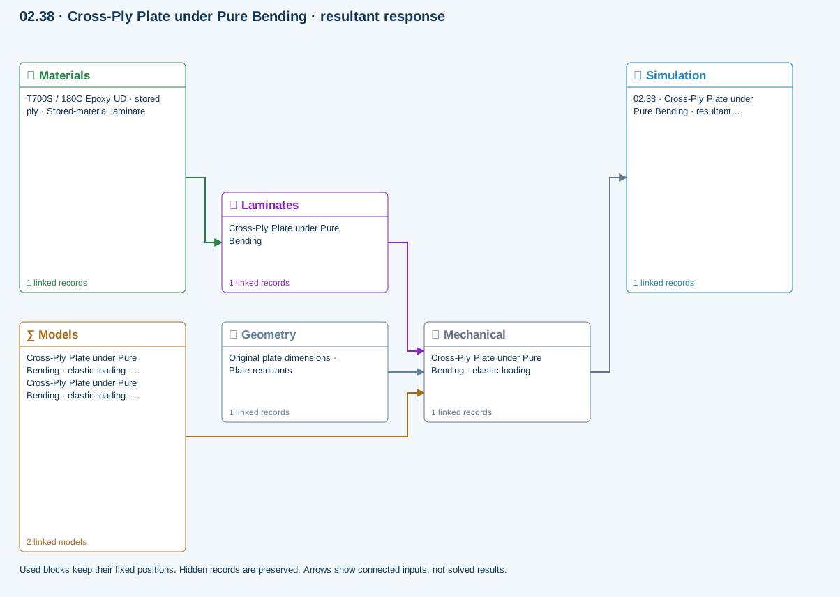
Materials → Laminates: Stored ply stiffness, strength, density and expansion properties.
Mechanical → Simulation: SIMULATION selects this case and its analysis model; the case owns its applicable cycle and input references.
Laminates → Mechanical: Ply angles and thicknesses, stiffness, mass and ply properties.
Geometry → Mechanical: Part shape and dimensions, thickness or section definition, and model-specific geometric inputs. Each selected case consumes only the dimensions its model supports.
Models → Mechanical: Applied model assignment: CLT · Linear static with failure indices. Model parameters and formulation are used by Mechanical.; Maximum stress
Further reading and evidence
- Edit material properties and units
- Edit laminate materials, angles and thicknesses
- Run and review a model
- Review effective properties
- Connected inputs and result freshness
- Geometry, loading and virtual tests
Review the recorded validation scope. Retain the original inputs and solver notices with the results. Representative teaching data are not design allowables.
References and source sections
References are retained with the formulations they support. Software instructions describe implementation scope; a cited source does not establish independent validation of a CDS calculation.