
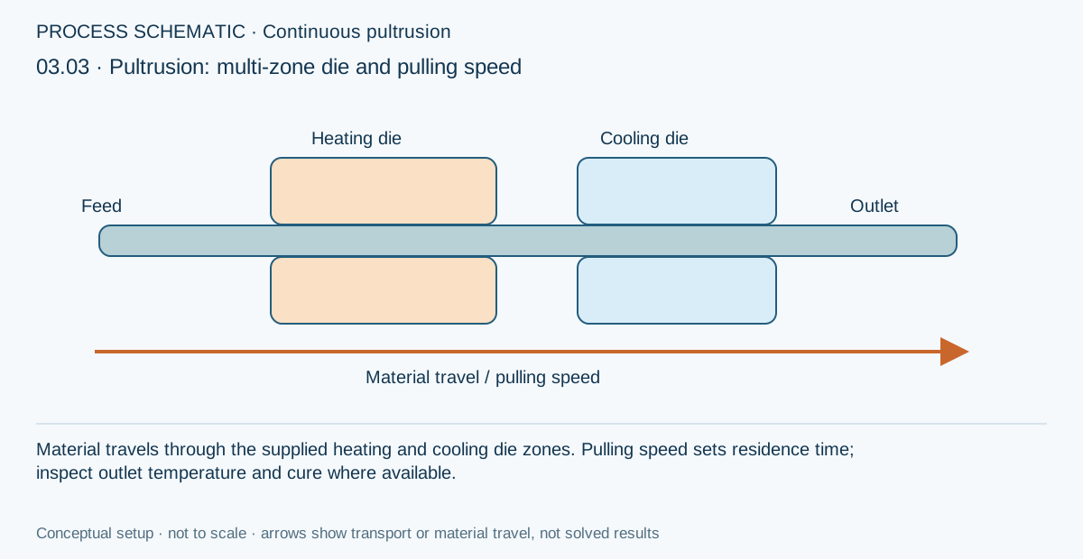
In a pultrusion study, pulling speed connects a position along the die to the time experienced by a moving material section. The exercise uses that relationship to examine residence time, heating and cure, with a structural comparison only where the selected simulation supports that transfer.
Open this exercise in Workbench
Prepare the baseline
Check the die length, inlet state, pulling speed and boundary stations before changing between length and time views. Keep the intended coordinate basis fixed while comparing speeds. Record the computed outlet state for each run; a prescribed die temperature is not an imposed core temperature or a guarantee of complete cure.
Worked procedure
1. In SIMULATION, select the thermal case and inspect its linked laminate. In Incoming material conditions, identify pulling velocity 0.1 m/min and inlet temperature 23°C; the calculated outlet is not a prescribed material temperature.
2. Open Equipment below Geometry and inspect the linked upper/lower heating dies at 80°C over 0–0.4 m, 150°C over 0.4–1.0 m and 180°C over 1.0–1.4 m, followed by 40°C cooling dies over 1.4–1.6 m. Review body temperature, contact conductance and dimensions; Thermal → Upper/Lower holds placement and station limits. Tool temperatures are prescribed hardware setpoints, not material temperatures.
3. Run and inspect surface/core temperature, cure, axial-position cursor, residence time and balanced inlet/outlet mass flux. Reaction heating uses the linked resin data.
4. Keep Length selected and compare 0.05, 0.1 and 0.2 m/min. Record outlet core temperature and cure, and compare residence times 32, 16 and 8 min.
Review checkpoints
At 0.1 m/min, 1.6 m corresponds to 16 min.
Heating and cooling die records are in Equipment. Editing a die temperature updates its connected boundary; moving a die changes the active contact footprint. Composite temperature is solved, not clamped to the die setpoint.
Mass flux in equals mass flux out and is reported per unit cross-sectional area, not total mass flow. Increasing speed increases flux and reduces residence time.
Repeat with more thickness nodes and a shorter output interval to assess discretization sensitivity; do not infer a pass from the exercise completing.
Model limits
Hypothetical teaching process using existing T700/epoxy laminate properties and illustrative cure parameters, not a calibrated pultrusion recipe. Constant-speed moving section; no axial conduction, impregnation, leakage, die thermal mass or pulling-force prediction. Use Thermal Run, not batch-cycle optimization.
Interpret the comparison
Explain the process result using the reported residence time and surface/core histories. For coupled variants, also record the actual state and stiffness passed into the structural calculation. Separate changes caused by section thickness or applied load from changes caused by cure, and do not infer an acceptable production speed without calibrated requirements.
How information passes between models
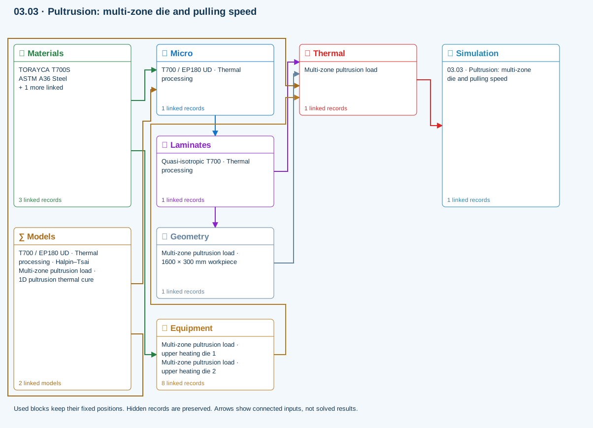
Micro → Laminates: Predicted ply stiffness, strength, density and expansion properties.
Laminates → Geometry: Ply angles and thicknesses, stiffness, mass and ply properties.
Materials → Equipment: Constituent stiffness, strength, density and thermal / moisture properties.
Materials → Micro: Constituent stiffness, strength, density and thermal / moisture properties.
Thermal → Simulation: SIMULATION selects this case and its analysis model; the case owns its applicable cycle and input references.
Laminates → Thermal: Ply angles and thicknesses, stiffness, mass and ply properties.
Geometry → Thermal: Part shape and dimensions, thickness or section definition, and model-specific geometric inputs. Each selected case consumes only the dimensions its model supports.
Equipment → Thermal: Linked lasers, IR/UV lamps, heaters, coolers and molds: dimensions, radiant power or prescribed temperature / heat flux, contact conductance, body and surface materials. Each boundary keeps its own placement, side and exposure.
Models → Micro: Applied model assignment: Halpin–Tsai. Model parameters and formulation are used by Micro.
Models → Thermal: Applied model assignment: 1D pultrusion thermal cure. Model parameters and formulation are used by Thermal.
Further reading and evidence
- Connect a simulation
- Edit material properties and units
- Enter a process cycle and boundary conditions
- Run and review a model
- Cure exotherm and evolving modulus
- Connected inputs and result freshness
- Related case study: NASA process cure
Review the recorded validation scope. Retain the original inputs and solver notices with the results. Representative teaching data are not design allowables.
References and source sections
References are retained with the formulations they support. Software instructions describe implementation scope; a cited source does not establish independent validation of a CDS calculation.