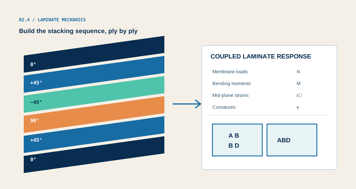
Ply stack
Set each ply’s material reference, angle and thickness. These choices define the laminate stiffness, mass and reference properties.
Capabilities / 02.4
Build the stacking sequence from stored or Micro-derived ply properties. Then choose a compatible structural or separate analytical study to check the response you need.
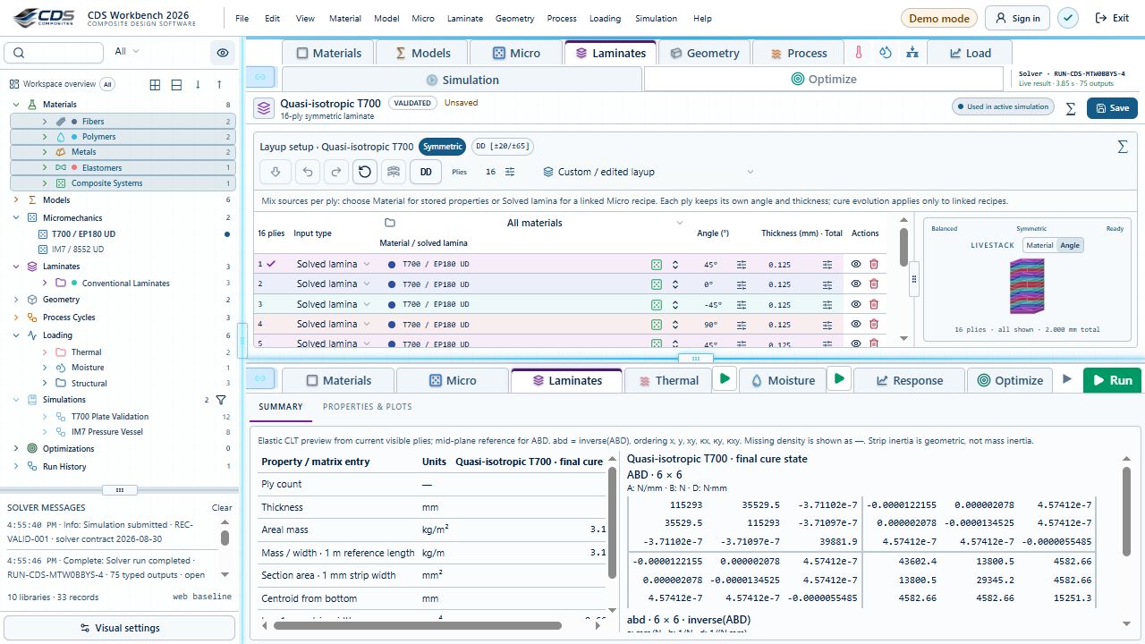
A 16-ply laminate using a linked Micro recipe. The live stack is colored by ply angle, alongside the shared CLT properties.
Workbench capture · September 10, 2026. This capture shows the interface with demo data. It is not a new solver run or a validation certificate. Control locations may differ in later releases.Connected study preview, not a live calculation. Edit inputs and inspect results in Workbench.
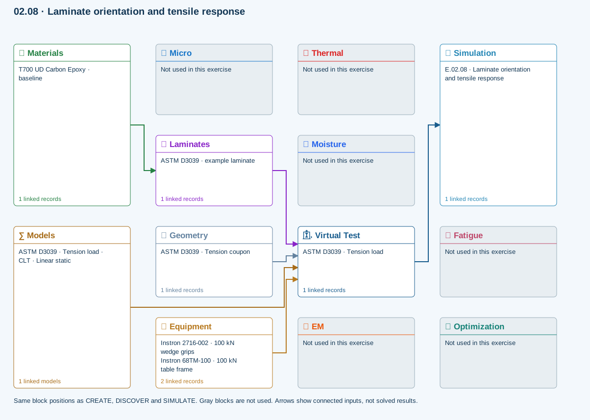
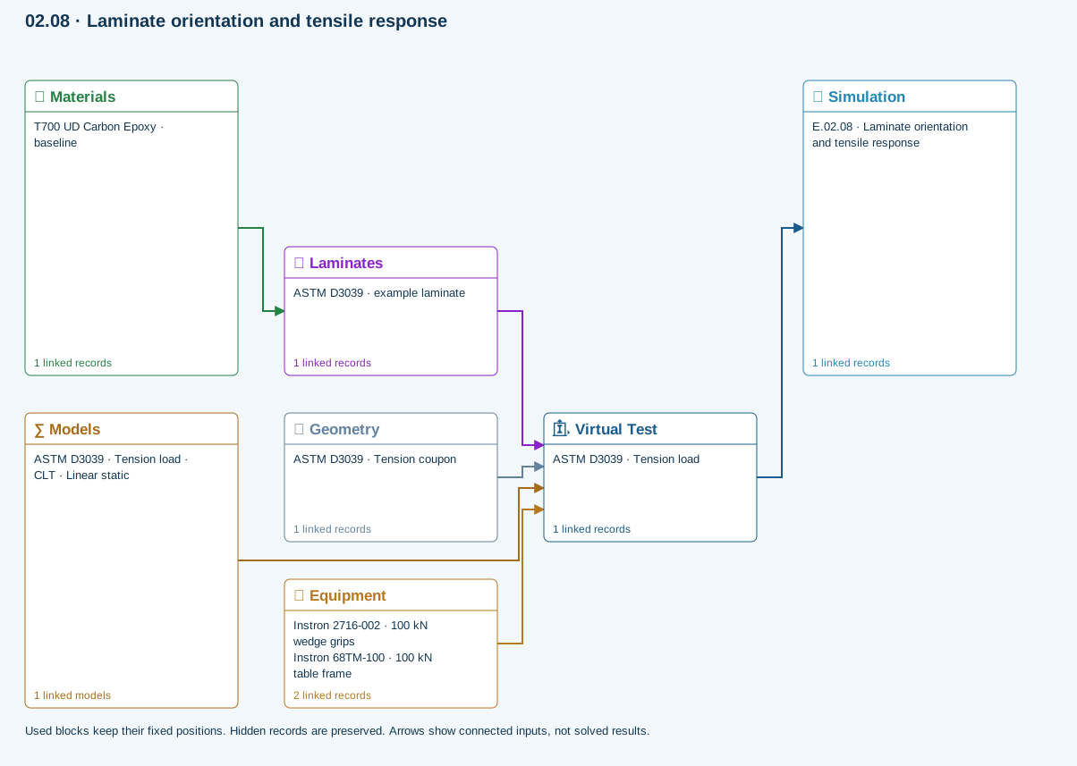
All blocks keep the CREATE / DISCOVER / SIMULATE positions, with Equipment below Geometry; unused records remain disconnected. This changes the view only, not the exercise records. The diagram shows the setup, not solved results.
Only models assigned to records used by this exercise are listed here. The full-layout option preserves the supplied starter records; no Workbench records are changed.
Shared laminate stiffness drives this membrane/CLT path. Failure criteria are independent comparisons, not blended models. Fatigue is a separate assessment.
∑ Theory & assumptionsMaterials → Laminates
Stored ply stiffness, strength, density and expansion properties.
Virtual Test → Simulation
SIMULATION selects this case and its analysis model; the case owns its applicable cycle and input references.
Laminates → Virtual Test
Ply angles and thicknesses, stiffness, mass and ply properties.
Geometry → Virtual Test
Part shape and dimensions, thickness or section definition, and model-specific geometric inputs. Each selected case consumes only the dimensions its model supports.
Equipment → Virtual Test
Linked testing machine and fixture: load capacities, fixture type, specimen-fit and support-span limits, and mounted setup dimensions. The selected test case supplies the applied loading; hardware limits are checked against its setup.
Models → Virtual Test
Applied model assignment: CLT · Linear static. Model parameters and formulation are used by Virtual Test.
Open the copied laminate and record the initial stacking sequence and total thickness.
Models: Classical laminate theory · Linear static · ASTM D3039-17(2025)-based
ASTM-based teaching geometry, not certification. Grips, tabs, alignment and physical test validity are not simulated.
02.4 / How to use it
What to set, compare and checkSet each ply’s material reference, angle and thickness. These choices define the laminate stiffness, mass and reference properties.
ABD properties support laminate response. Finite-plate studies select CLT or FSDT within their supported boundary and study limits; static plate bending requires FSDT.
Eligible CLT cases use the released failure criteria. Coupled delamination belongs to the supported layerwise section path with calibrated interfaces, not every plate solver.
Open-hole strength, linear-shear LaRC04 initiation, axial creep and uncertainty use the linked laminate reference state. They do not automatically inherit process or progressive-damage histories.
Use carpet maps and bounded optimization to compare candidates. After applying a candidate, rerun the appropriate analysis so the saved result reflects the new inputs.
Explore the models, connections and theory →
What to check and where it applies