
Not every laminate needs a micromechanics calculation. This exercise helps you read a stored material or mixed-source stack correctly, tracing each ply back to the properties it actually uses. The distinction matters when historical records, measured properties and calculated Micro recipes appear in the same workspace.
Open this exercise in Workbench
Prepare the baseline
Follow the material reference for each ply and inspect its units, status and source before running. For converted records, distinguish the original data from any teaching loads added during conversion. Establish the baseline response first, then make the comparison specified below without also changing unrelated material properties or boundary conditions.
Worked procedure
1. Inspect the alternating ply sources in the stack, distinguishing the stored-material plies from those whose properties come from a solved Micro recipe. Confirm their respective 0.15/0.10 mm thicknesses and record the total stack thickness. This source-by-source check is important because a shared laminate can contain more than one route to its ply properties.
2. Run the mixed-source stack and retain the laminate properties and the relevant response outputs. Compare these with the uniform stored-material and solved-Micro examples, noting differences in ply source, sequence and thickness before drawing a conclusion. Explain which aspects of the comparison can be attributed to material properties and which also reflect a change in the stack.
Review checkpoints
The sixteen plies total 2 mm.
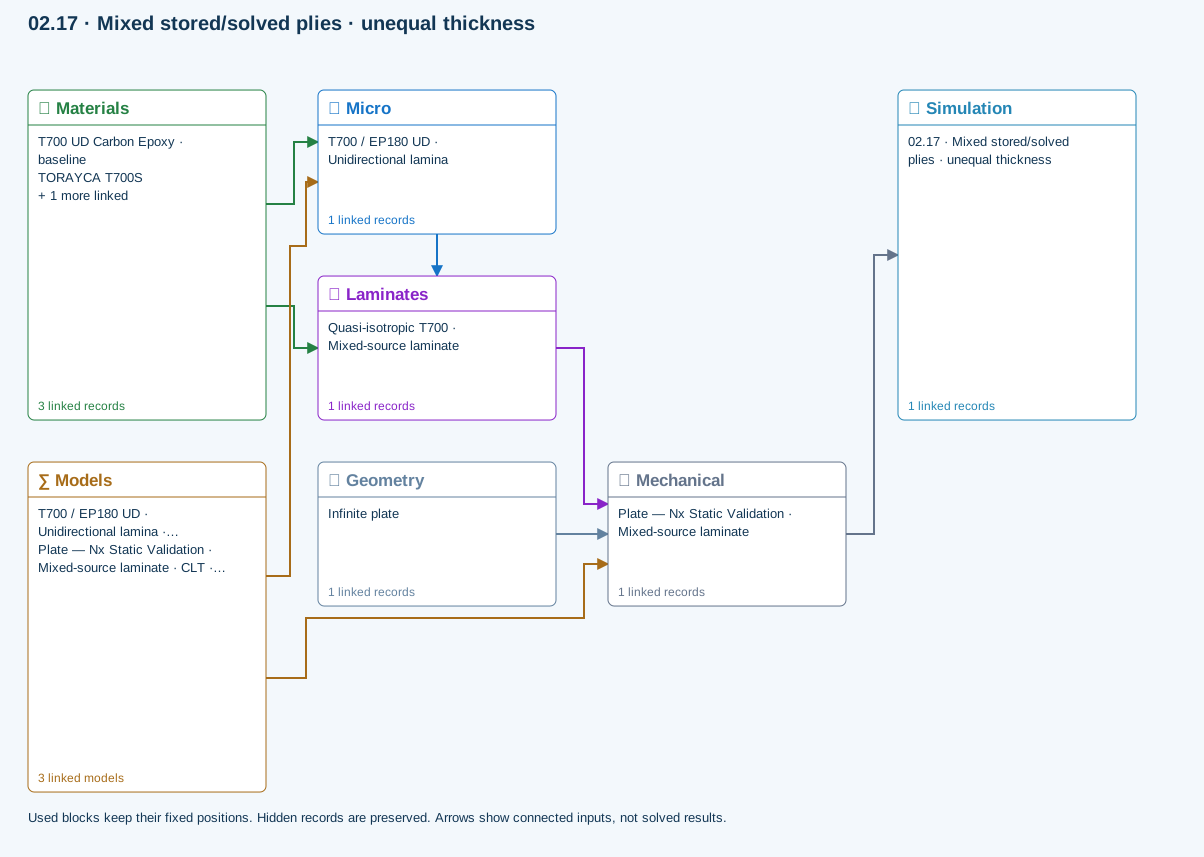
Both direct material and solved Micro paths feed the laminate.
Model limits
Reference-state elastic laminate comparison; different ply sources and thicknesses are intentional. Representative properties are not qualified allowables.
Interpret the comparison
Use stiffness, strain, curvature and ply-stress outputs together to explain the load response. Where the task doubles a resultant, compare the resulting change with the stated linear model and unchanged reference state. Do not infer missing strengths, a progressive loading history or validation evidence from the presence of an older source file.
How information passes between models
Micro → Laminates: Predicted ply stiffness, strength, density and expansion properties.
Materials → Laminates: Stored ply stiffness, strength, density and expansion properties.
Materials → Micro: Constituent stiffness, strength, density and thermal / moisture properties.
Mechanical → Simulation: SIMULATION selects this case and its analysis model; the case owns its applicable cycle and input references.
Laminates → Mechanical: Ply angles and thicknesses, stiffness, mass and ply properties.
Geometry → Mechanical: Part shape and dimensions, thickness or section definition, and model-specific geometric inputs. Each selected case consumes only the dimensions its model supports.
Models → Micro: Applied model assignment: Halpin–Tsai. Model parameters and formulation are used by Micro.
Models → Mechanical: Applied model assignment: CLT · Linear static with failure indices. Model parameters and formulation are used by Mechanical.; Maximum stress
Further reading and evidence
- Connect a simulation
- Edit laminate materials, angles and thicknesses
- Run and review a model
- Connected inputs and result freshness
- Related case study: NASA laminate design
Review the recorded validation scope. Retain the original inputs and solver notices with the results. Representative teaching data are not design allowables.
References and source sections
References are retained with the formulations they support. Software instructions describe implementation scope; a cited source does not establish independent validation of a CDS calculation.