
An axial load applied to an angle-ply specimen produces a combination of stresses in the ply material axes. The purpose of this exercise is to follow that coordinate transformation and understand why a nominal specimen-level shear measure must be compared with the appropriate output rather than any quantity labelled shear.
Open this exercise in Workbench
Prepare the baseline
Check the balanced layup, specimen dimensions and applied force before running. Keep global strains, global stresses and ply-axis stresses in separate columns in your notes. When using the nominal expression supplied in the task, identify the width and thickness used in its denominator and keep their units consistent.
Worked procedure
1. Inspect the balanced ±45° laminate and its axial tensile load.
2. Run and inspect material-axis shear stresses and global strains.
3. Compare nominal shear stress P/(2bt) with the applicable output and explain the coordinate transformation.
Review checkpoints
The applied load is axial tension, not a directly applied global shear force.
Keep the distinction between global strains and material-axis shear strain.
Model limits
Small-strain elastic teaching model; fibre rotation and nonlinear termination rules are not represented.
Interpret the comparison
Explain how the orientation of the plies connects the imposed loading to the recovered shear response. If quantities differ, first check their coordinate systems and whether they are nominal or local values. The numerical exercise illustrates an idealized response; it does not replace the specimen preparation, measurements or acceptance requirements of a physical test.
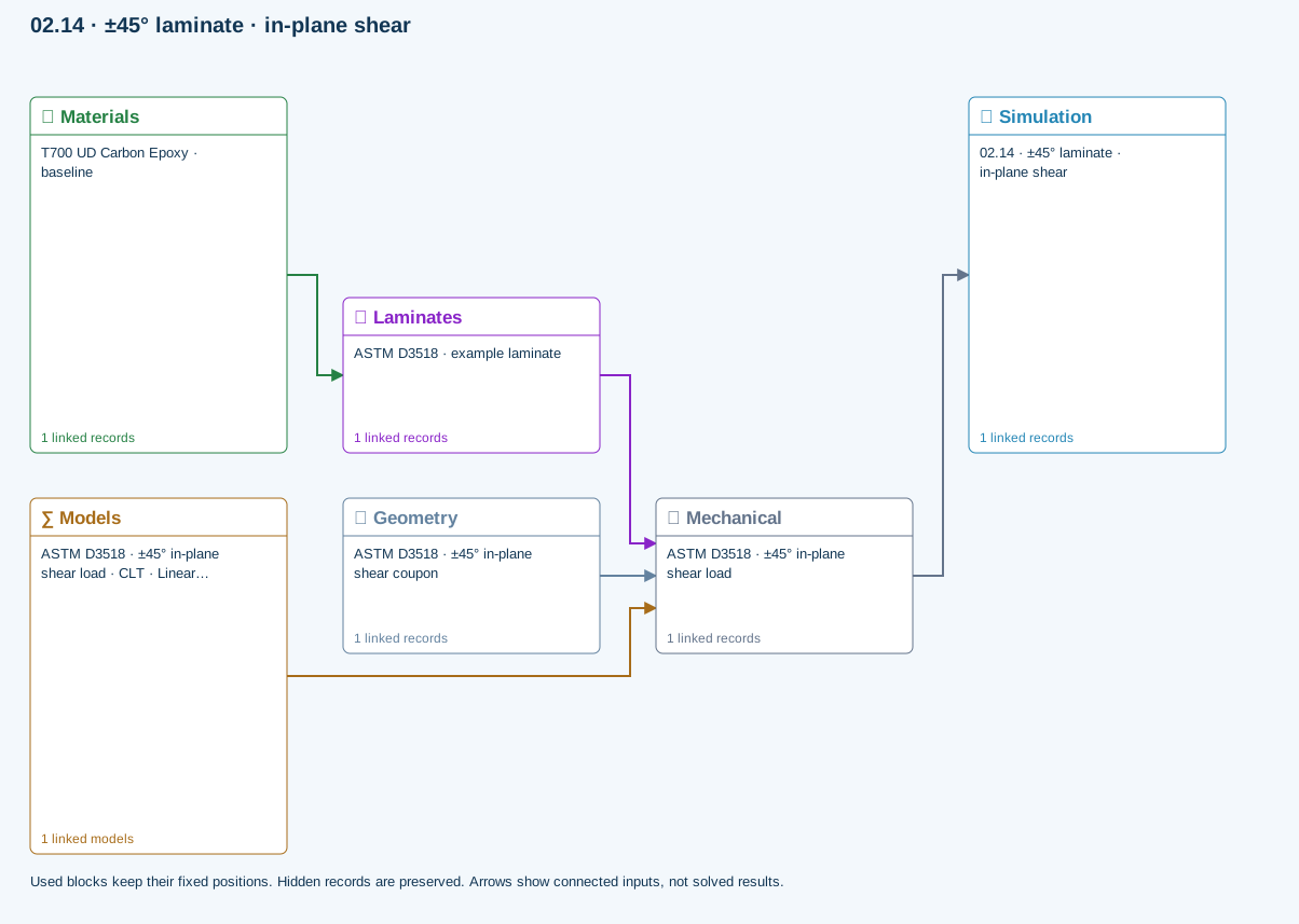
How information passes between models
Materials → Laminates: Stored ply stiffness, strength, density and expansion properties.
Mechanical → Simulation: SIMULATION selects this case and its analysis model; the case owns its applicable cycle and input references.
Laminates → Mechanical: Ply angles and thicknesses, stiffness, mass and ply properties.
Geometry → Mechanical: Part shape and dimensions, thickness or section definition, and model-specific geometric inputs. Each selected case consumes only the dimensions its model supports.
Models → Mechanical: Applied model assignment: CLT · Linear static. Model parameters and formulation are used by Mechanical.
Further reading and evidence
- Edit laminate materials, angles and thicknesses
- Geometry, loading and virtual tests
- Run and review a model
- Review effective properties
- Related case study: NASA laminate design
Review the recorded validation scope. Retain the original inputs and solver notices with the results. Representative teaching data are not design allowables.
References and source sections
References are retained with the formulations they support. Software instructions describe implementation scope; a cited source does not establish independent validation of a CDS calculation.