
Bending response depends on both the laminate and the way it is supported and loaded. This exercise keeps those ingredients explicit so that you can relate a change in span to the calculated deformation and stress distribution, rather than treating deflection as a material property by itself.
Open this exercise in Workbench
Prepare the baseline
Inspect the support span, specimen length, width, thickness and central force before the first run. Record the baseline deflection and the locations of the reported ply stresses. Make the prescribed span change while preserving adequate specimen length and the other inputs, then compare the same output locations and units.
Worked procedure
1. Inspect specimen width, laminate thickness, support span and central force.
2. Run and inspect the deflection plot and ply stresses.
3. Change support span by 20% while maintaining sufficient specimen length, rerun, and compare peak deflection.
Review checkpoints
Check the support and loading graphic against the setup.
For unchanged effective EI and load, beam deflection scales with span cubed.
Model limits
Procedure A teaching setup. Transverse shear deformation, roller contact and indentation are excluded.
Interpret the comparison
Discuss deformation and stress separately, since they answer different engineering questions. Include the geometry and support arrangement with any saved plot, and state the assumptions of the selected beam or laminate formulation. Do not extend the result to contact damage or other behaviour that is outside the model.
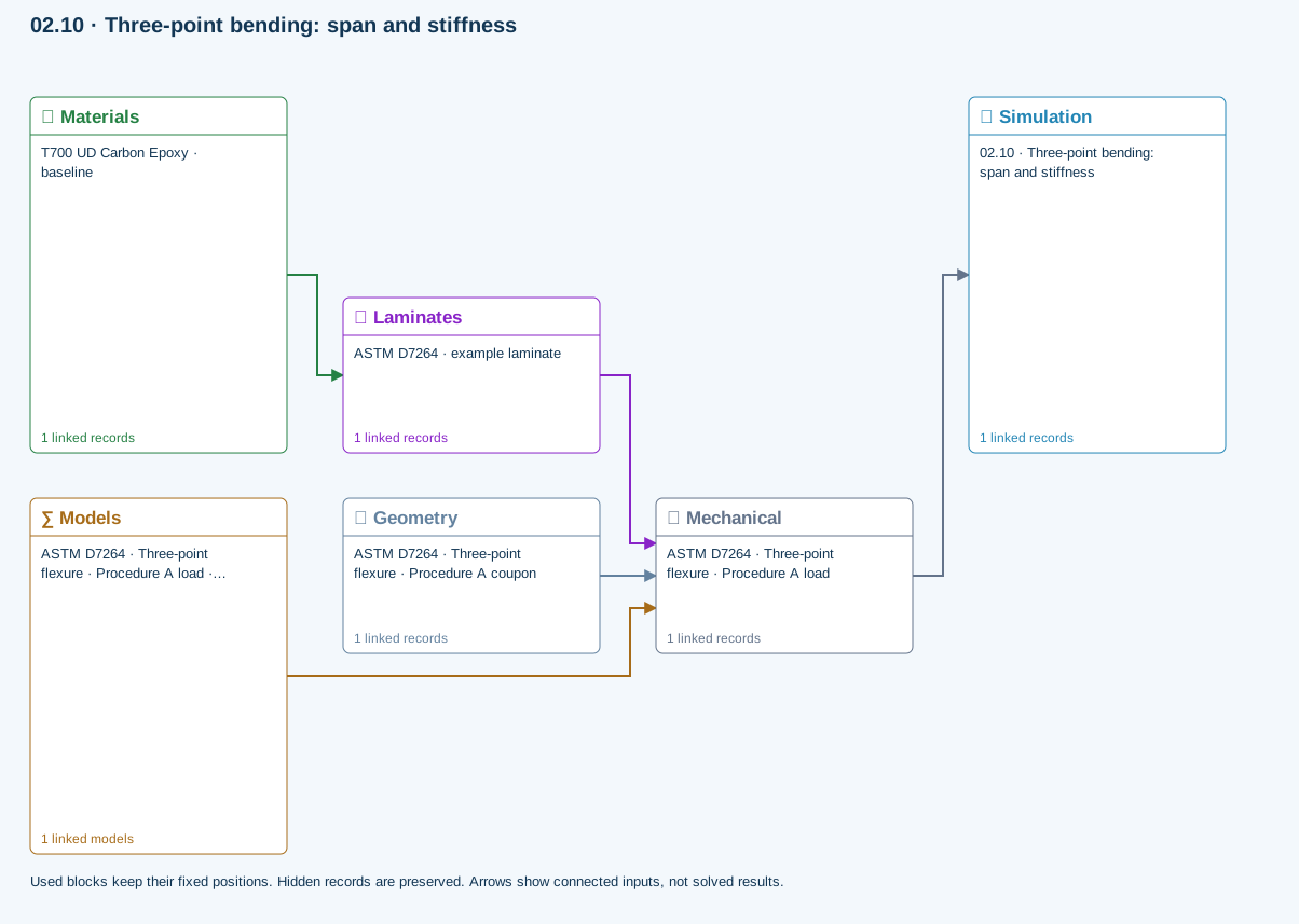
How information passes between models
Materials → Laminates: Stored ply stiffness, strength, density and expansion properties.
Mechanical → Simulation: SIMULATION selects this case and its analysis model; the case owns its applicable cycle and input references.
Laminates → Mechanical: Ply angles and thicknesses, stiffness, mass and ply properties.
Geometry → Mechanical: Part shape and dimensions, thickness or section definition, and model-specific geometric inputs. Each selected case consumes only the dimensions its model supports.
Models → Mechanical: Applied model assignment: Euler–Bernoulli beam · Linear static. Model parameters and formulation are used by Mechanical.
Further reading and evidence
- Geometry, loading and virtual tests
- Edit laminate materials, angles and thicknesses
- Run and review a model
- Connected inputs and result freshness
Review the recorded validation scope. Retain the original inputs and solver notices with the results. Representative teaching data are not design allowables.
References and source sections
References are retained with the formulations they support. Software instructions describe implementation scope; a cited source does not establish independent validation of a CDS calculation.