
A stacking sequence redistributes load between differently oriented plies. This exercise uses a controlled laminate comparison to show how that redistribution changes the overall stiffness and the stresses carried by individual plies, even when the constituent material remains the same.
Open this exercise in Workbench
Prepare the baseline
Record the initial ply order, angles and total thickness, then run the baseline before creating alternatives. Preserve the loading and geometry specified in the task so that the layup comparison remains meaningful. Inspect the laminate stiffness together with material-axis ply stresses; global stiffness alone does not show which ply is most highly stressed.
Worked procedure
1. Open the copied laminate and record the initial stacking sequence and total thickness.
2. Run the tensile example, then compare symmetric cross-ply and balanced ±45° stacks at the same thickness.
3. Review laminate stiffness and ply stresses; keep force and specimen width unchanged.
Review checkpoints
Geometry supplies the finite coupon width; the load is a total force.
A symmetric layup should have negligible extension–bending coupling.
Model limits
ASTM-based teaching geometry, not certification. Grips, tabs, alignment and physical test validity are not simulated.
Interpret the comparison
Explain the response in terms of orientation, symmetry and load sharing. Where a published stiffness comparison is provided, use it for that comparison only and retain the source’s qualification of the data. A match in elastic response is not an exact strength prediction, and a first-ply calculation should not be described as ultimate structural collapse.
How information passes between models
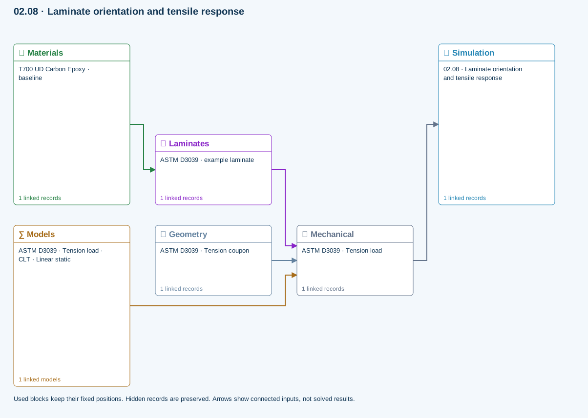
Materials → Laminates: Stored ply stiffness, strength, density and expansion properties.
Mechanical → Simulation: SIMULATION selects this case and its analysis model; the case owns its applicable cycle and input references.
Laminates → Mechanical: Ply angles and thicknesses, stiffness, mass and ply properties.
Geometry → Mechanical: Part shape and dimensions, thickness or section definition, and model-specific geometric inputs. Each selected case consumes only the dimensions its model supports.
Models → Mechanical: Applied model assignment: CLT · Linear static. Model parameters and formulation are used by Mechanical.
Further reading and evidence
- Edit laminate materials, angles and thicknesses
- Apply symmetry and balance
- Run and review a model
- Review effective properties
- Geometry, loading and virtual tests
- Related case study: NASA laminate design
Review the recorded validation scope. Retain the original inputs and solver notices with the results. Representative teaching data are not design allowables.
References and source sections
References are retained with the formulations they support. Software instructions describe implementation scope; a cited source does not establish independent validation of a CDS calculation.