
The stacking sequence connects local material behaviour with structural response. Enter the correct property source, angle and thickness for each layer, then check the resulting stiffness and any intended symmetry. For sandwich constructions, the core has a distinct physical role; its thickness and shear properties should not be treated as an incidental extension of a face ply.
4.1 Turn ply definitions into laminate decisions.
Workflow / 03.3 Laminates
Connect stored or Micro-derived ply properties to a stacking sequence, then choose a compatible structural or separate analytical study.
Connected model layer
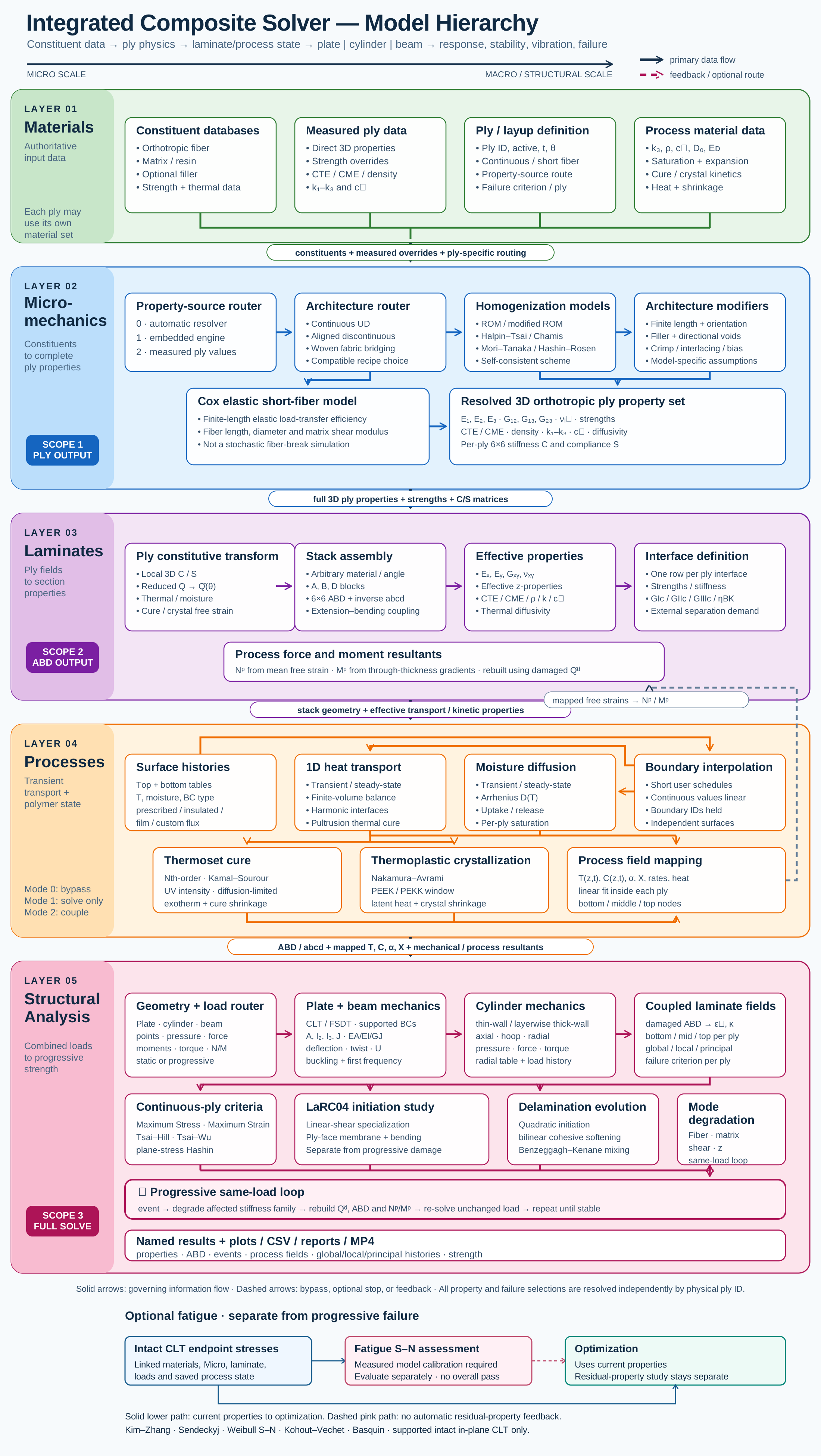
Laminates model map
Select a block to explore its theory or workflow. View the complete Model Map
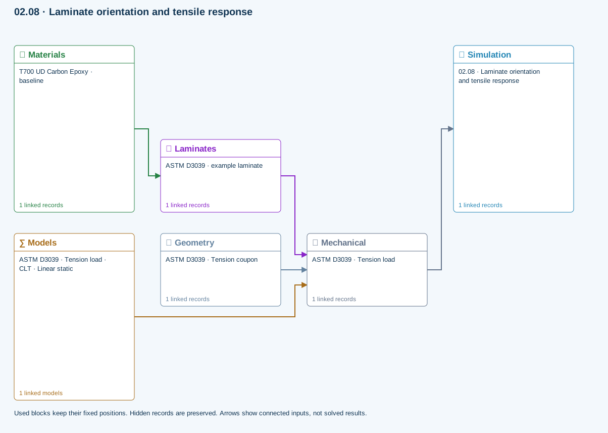
02.08 · Laminate orientation and tensile response
Level 2DevelopingEst. 25 min
Only blocks on the exercise path are shown. This changes the view only, not the exercise records.
∑ Used models & submodels
Only models assigned to records used by this exercise are listed here. The full-layout option preserves the supplied starter records; no Workbench records are changed.
CLT · Linear static · ASTM D3039 · Tension load
Shared laminate stiffness drives this membrane/CLT path. Failure criteria are independent comparisons, not blended models. Fatigue is a separate assessment.
∑ Theory & assumptionsData travelling between blocks
Materials → Laminates
Stored ply stiffness, strength, density and expansion properties.
Mechanical → Simulation
SIMULATION selects this case and its analysis model; the case owns its applicable cycle and input references.
Laminates → Mechanical
Ply angles and thicknesses, stiffness, mass and ply properties.
Geometry → Mechanical
Part shape and dimensions, thickness or section definition, and model-specific geometric inputs. Each selected case consumes only the dimensions its model supports.
Models → Mechanical
Applied model assignment: CLT · Linear static. Model parameters and formulation are used by Mechanical.
Open the copied laminate and record the initial stacking sequence and total thickness.
Models: Classical laminate theory · Linear static · ASTM D3039-based
Study scope and limitations
ASTM-based teaching geometry, not certification. Grips, tabs, alignment and physical test validity are not simulated.
03.3 / Workflow focus
Connected engineering recordPly stack
Set material references, angles and thicknesses. The stack defines laminate stiffness, mass and reference properties.
CLT and FSDT
ABD properties support laminate response. Finite-plate studies select CLT or FSDT within their supported boundary and study limits; static plate bending requires FSDT.
Failure and interfaces
Eligible CLT cases use the released failure criteria. Coupled delamination belongs to the supported layerwise section path with calibrated interfaces, not every plate solver.
Separate analytical studies
Open-hole strength, linear-shear LaRC04 initiation, axial creep and uncertainty use the linked laminate reference state. They do not automatically inherit process or progressive-damage histories.
Design exploration
Carpet maps and bounded optimization compare candidates. Apply a candidate and rerun the appropriate analysis; a saved result does not update itself.
Use this workflow in Workbench: interactive Blocks, record selections and connection controls →
Connected model layer
Laminates · released model connections
Select a model family to follow its inputs, results, theory and exercise. All model families ↗
Follow the connections
Structural mechanics
Laminate & geometry
Laminate stiffness, finite plate dimensions, supported edges and study choice
Load response / stability
Displacements, stresses & modes
FSDT static bending or selected buckling / modal results; not progressive damage
Representative exercise: this map shows its supplied records and active connections, not every possible configuration of the model family.
Only blocks on the exercise path are shown. This changes the view only, not the exercise records.
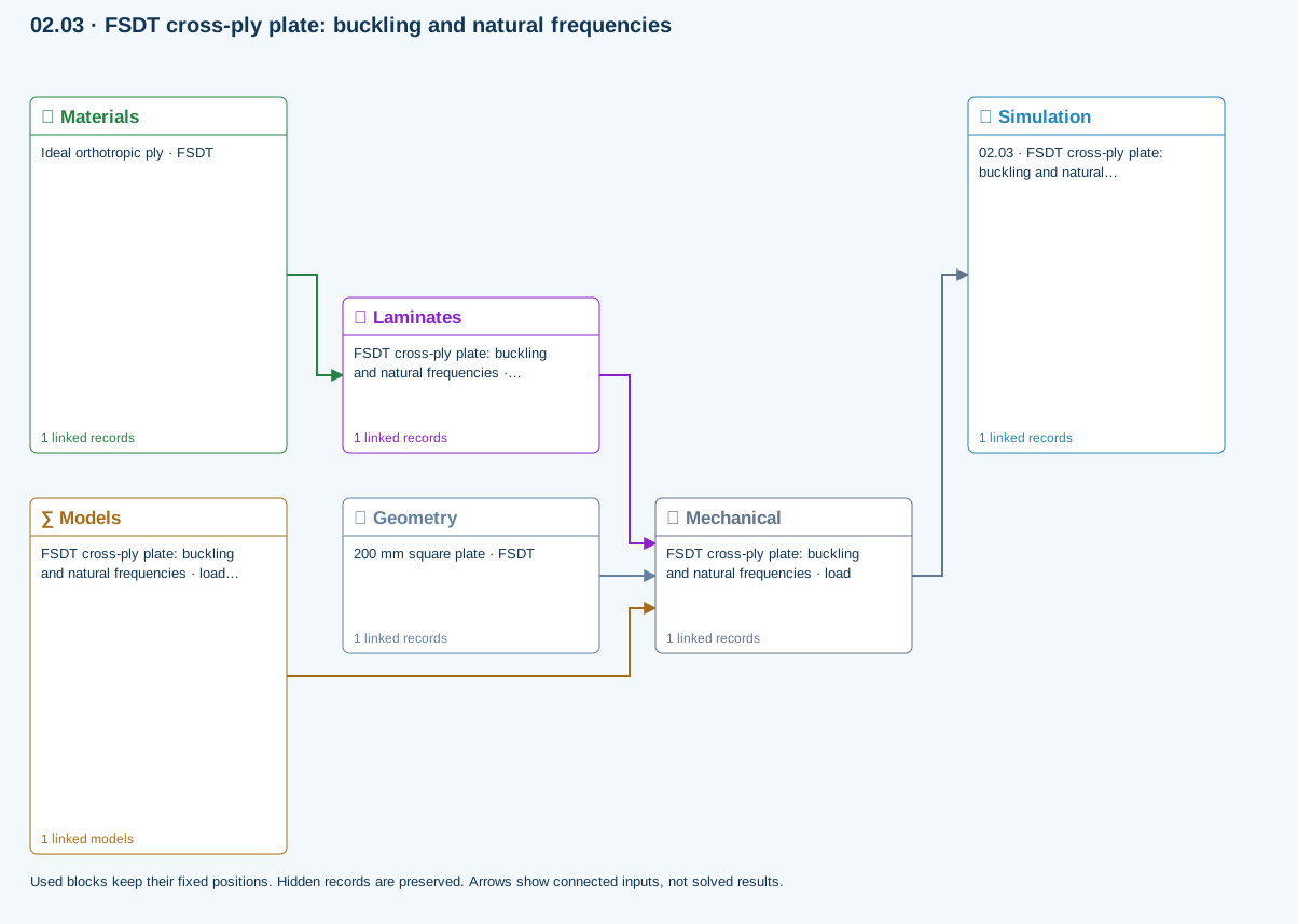
Plate · CLT & FSDT
Choose a formulation and study. Buckling and modal can be requested together; static bending requires FSDT. These are reference-elastic studies, separate from coupled process or progressive failure.
Model choices and Workbench location
Structural models → Laminate mechanics · CLT / FSDT
- CLT
- FSDT
- Static bending
- Modal
- Buckling
- Buckling and modal
Chapter review
A checked laminate has traceable layer definitions and a total thickness consistent with the intended structure.
References and source sections
References are retained with the formulations they support. Software instructions describe implementation scope; a cited source does not establish independent validation of a CDS calculation.