
A completed calculation is the beginning of interpretation. Check dimensions, limiting behaviour and applicable equilibrium or conservation relations before comparing with a reference. When a published test is used, match geometry, conditioning and loading as well as the material name. Record discrepancies rather than concealing them in a rounded value or a cropped plot.
7.1 Verification methods and evidence
04.14 / CDS User Guide
Recorded production-solver comparisons against published equations and source-matched public calculations.
06.1 Manuals · read online, preview or download →
Study 2026-09-20
138 of 138 exercise baselines executed. 42 passed scoped analytical comparisons; 0 have benchmark discrepancies; 96 have no completed quantitative benchmark; 0 failed execution.
No exercise has experimental validation from this study. A successful run, supplier property or similar-looking plot is not validation. Badges apply only to the listed outputs, recorded inputs and solver revision. Edited inputs and new solver revisions require revalidation.
Case combination regression checks
On 18 September 2026, 52,416 discrete catalog case-selector combinations, including None, were checked against selection compatibility rules: 406 were accepted and 52,010 rejected. These are selection checks, not numerical solutions of every combination. All seven nonempty thermal, moisture and mechanical subsets of the T700 starter executed successfully. Geometry dependency, model-pairing and stale-result checks also passed. This does not validate every material, geometry, load magnitude or coupled physical response.
Method and acceptance
Production solver executed on immutable copies of every exercise. Independent published-equation references use exact baseline inputs where eligible. Scoped analytical badges are not experimental validation, strength approval or validation of edited inputs. Full coupled studies remain unvalidated until matched external evidence and convergence studies exist. Tolerances were declared before numerical comparisons: analytical constants 0.01% + 0.00002 units; beam/strain 0.05% + absolute allowance; rounded NASA table values 1% + 0.00002.
Each validation data panel states its quantities, predeclared tolerances and sources. Independent laminate references use strain/stress coordinate transformations and thickness integration, not production stiffness helpers. Separate NASA fixtures use the report's numerical inputs; they do not confer validation on the unmatched exercise starter.
Findings and outstanding work
- The recorded thin-wall pressure cases pass scoped equilibrium and orthotropic biaxial strain comparisons, including Poisson coupling. This is not a blanket validation of every pressure-vessel exercise or of unverified micromechanics inputs; use each validation data panel for its tested scope.
- The NASA tube fixture matches three published calculated stiffness properties within 1%. This is not an experimental strength or failure validation.
- NASA MAC/GMC micro-property comparisons do not all match the CDS ROM/Halpin–Tsai models. Different model formulations and their discrepancies are retained, not hidden.
- Coupled cure, UV, pultrusion, moisture, sandwich/bonding and progressive delamination require matched constitutive data, boundary conditions, field measurements and convergence studies before a full coupled validation claim.
Download complete reproducible comparison validation data (JSON) · Search exercise tree
Use the study-level methods in this chapter to distinguish numerical verification from physical validation. Individual exercise evidence, comparison values and limitations remain with the online validation records and the corresponding training exercises; they are not repeated as an appendix to this operating guide. Before relying on a prediction, identify which comparison applies to the selected formulation, material and boundary conditions.
7.2 Turn model output into repeatable engineering results.
Capabilities / 02.7
CDS solves the handoff from analysis to decision by linking comparisons, fields, tables, parametric studies, and open exports across the complete composite model chain.
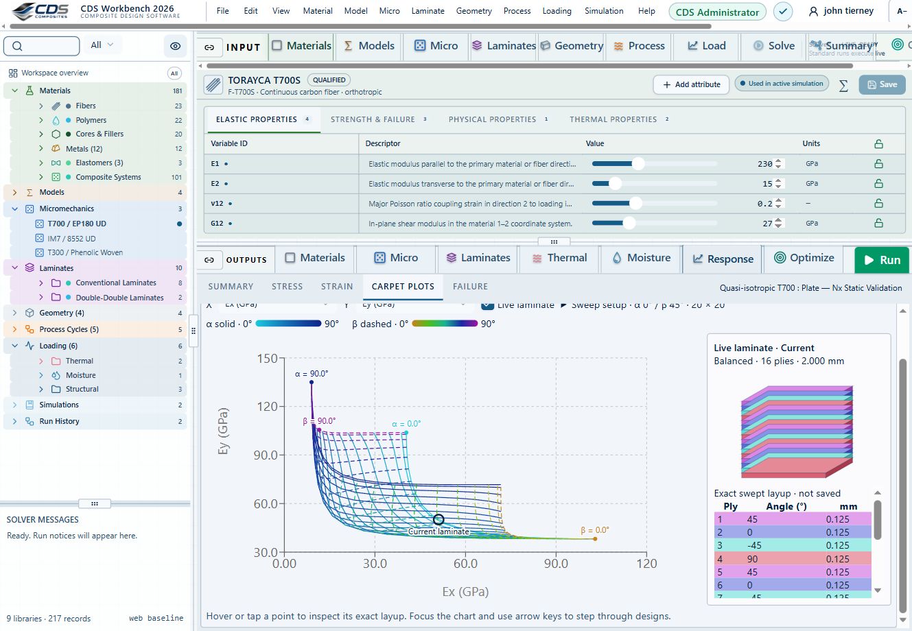
A linked carpet plot and laminate stack make the selected design visible alongside its properties.
Workbench capture · September 6, 2026. Representative interface and demo data, not a new solver run or validation certificate. Control locations may differ in later releases.02.10 · Three-point bending: span and stiffness
Level 3IntermediateEst. 25 min
Only blocks on the exercise path are shown. This changes the view only, not the exercise records.
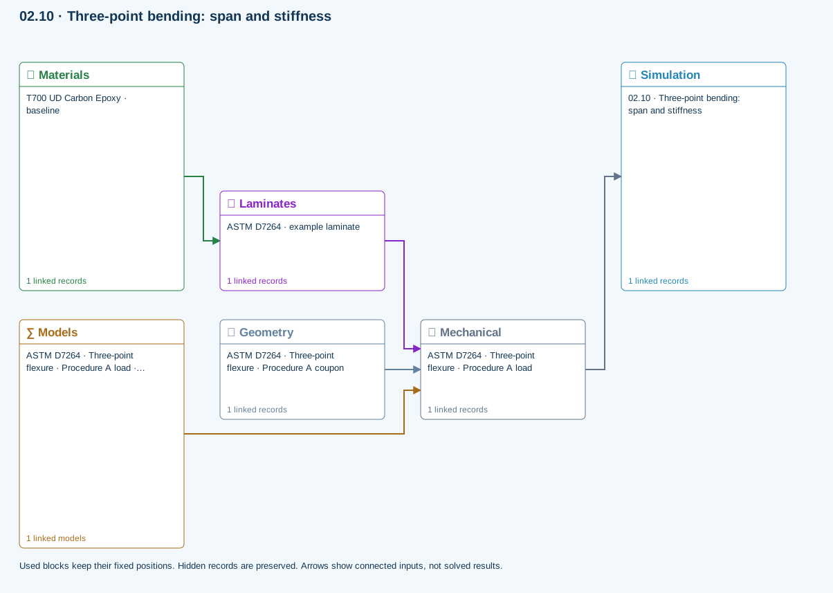
∑ Used models & submodels
Only models assigned to records used by this exercise are listed here. The full-layout option preserves the supplied starter records; no Workbench records are changed.
Euler–Bernoulli beam · Linear static · ASTM D7264 · Three-point flexure · Procedure A load
Beam bending uses effective laminate axial stiffness, the linked section geometry, support span and applied loading. Euler–Bernoulli deflection excludes transverse shear deformation, roller contact and indentation. Ply stress recovery for rectangular laminate coupons is separate from section-level beam stress recovery.
∑ Theory & assumptionsData travelling between blocks
Materials → Laminates
Stored ply stiffness, strength, density and expansion properties.
Mechanical → Simulation
SIMULATION selects this case and its analysis model; the case owns its applicable cycle and input references.
Laminates → Mechanical
Ply angles and thicknesses, stiffness, mass and ply properties.
Geometry → Mechanical
Part shape and dimensions, thickness or section definition, and model-specific geometric inputs. Each selected case consumes only the dimensions its model supports.
Models → Mechanical
Applied model assignment: Euler–Bernoulli beam · Linear static. Model parameters and formulation are used by Mechanical.
Inspect specimen width, laminate thickness, support span and central force.
Models: Euler–Bernoulli beam · ASTM D7264-based
Study scope and limitations
Procedure A teaching setup. Transverse shear deformation, roller contact and indentation are excluded.
02.7 / How CDS solves it
From engineering question to validation dataCompare properties
Select one or more materials, laminas, laminates, simulations or optimization snapshots and review scrollable tables, bar charts, Ashby plots, line plots, property maps, and laminate stiffness matrices.
Explore field response
Move result cursors through time and thickness to update linked thermal plots, or select stress, strain, displacement, resultant, and factor-of-safety views for a structural case.
Export the validation data
Right-click supported tables to save CSV or XLSX data and presentation-oriented PPTX output where available, or write supported material cards for downstream finite-element analysis.
Explore the models, connections and theory →
Outcomes and boundaries
- Results update from the active tree selection
- Charts and tables provide complementary views of the same solution
- Mechanical, thermal, moisture, and total response can be reviewed separately
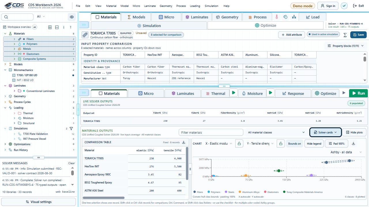
Controls and workflow details · 6 features
- Bar charts compare up to three properties; Ashby views compare any two
- Linear and logarithmic scales are available for property comparison
- Legend hover highlights its plotted records when practical
- 3D views provide fill, opacity, extrema and autoscale controls
- Thermal cursors link time-history and through-thickness plots
- Right-click supported tables to export CSV, XLSX or PPTX validation data
7.3 Turn model output into repeatable engineering results.
Capabilities / 02.7
CDS solves the handoff from analysis to decision by linking comparisons, fields, tables, parametric studies, and open exports across the complete composite model chain.
A linked carpet plot and laminate stack make the selected design visible alongside its properties.
Workbench capture · September 6, 2026. Representative interface and demo data, not a new solver run or validation certificate. Control locations may differ in later releases.02.10 · Three-point bending: span and stiffness
Level 3IntermediateEst. 25 min
Only blocks on the exercise path are shown. This changes the view only, not the exercise records.
∑ Used models & submodels
Only models assigned to records used by this exercise are listed here. The full-layout option preserves the supplied starter records; no Workbench records are changed.
Euler–Bernoulli beam · Linear static · ASTM D7264 · Three-point flexure · Procedure A load
Beam bending uses effective laminate axial stiffness, the linked section geometry, support span and applied loading. Euler–Bernoulli deflection excludes transverse shear deformation, roller contact and indentation. Ply stress recovery for rectangular laminate coupons is separate from section-level beam stress recovery.
∑ Theory & assumptionsData travelling between blocks
Materials → Laminates
Stored ply stiffness, strength, density and expansion properties.
Mechanical → Simulation
SIMULATION selects this case and its analysis model; the case owns its applicable cycle and input references.
Laminates → Mechanical
Ply angles and thicknesses, stiffness, mass and ply properties.
Geometry → Mechanical
Part shape and dimensions, thickness or section definition, and model-specific geometric inputs. Each selected case consumes only the dimensions its model supports.
Models → Mechanical
Applied model assignment: Euler–Bernoulli beam · Linear static. Model parameters and formulation are used by Mechanical.
Inspect specimen width, laminate thickness, support span and central force.
Models: Euler–Bernoulli beam · ASTM D7264-based
Study scope and limitations
Procedure A teaching setup. Transverse shear deformation, roller contact and indentation are excluded.
02.7 / How CDS solves it
From engineering question to validation dataCompare properties
Select one or more materials, laminas, laminates, simulations or optimization snapshots and review scrollable tables, bar charts, Ashby plots, line plots, property maps, and laminate stiffness matrices.
Explore field response
Move result cursors through time and thickness to update linked thermal plots, or select stress, strain, displacement, resultant, and factor-of-safety views for a structural case.
Export the validation data
Right-click supported tables to save CSV or XLSX data and presentation-oriented PPTX output where available, or write supported material cards for downstream finite-element analysis.
Explore the models, connections and theory →
Outcomes and boundaries
- Results update from the active tree selection
- Charts and tables provide complementary views of the same solution
- Mechanical, thermal, moisture, and total response can be reviewed separately
Controls and workflow details · 6 features
- Bar charts compare up to three properties; Ashby views compare any two
- Linear and logarithmic scales are available for property comparison
- Legend hover highlights its plotted records when practical
- 3D views provide fill, opacity, extrema and autoscale controls
- Thermal cursors link time-history and through-thickness plots
- Right-click supported tables to export CSV, XLSX or PPTX validation data
Chapter review
A report should identify the question, input state, result and limitations. Another reader should be able to distinguish the calculation from the engineering decision made from it.
References and source sections
References are retained with the formulations they support. Software instructions describe implementation scope; a cited source does not establish independent validation of a CDS calculation.