
A ply can obtain its properties from a stored material or from a micromechanics recipe. Both routes can be useful, but they have different provenance. After choosing the property source, the laminate requires an explicit angle and thickness for each layer. The stacking order is part of the model, because reversing or rearranging layers can change coupling even when total thickness is unchanged.
5.1 Build laminas and laminate families.
04.4 / CDS User Guide
Connect materials, edit compact ply stacks, review effective results, and create reusable material records.
06.1 Manuals · read online, preview or download →
02.08 · Laminate orientation and tensile response
Level 2DevelopingEst. 25 min
Only blocks on the exercise path are shown. This changes the view only, not the exercise records.
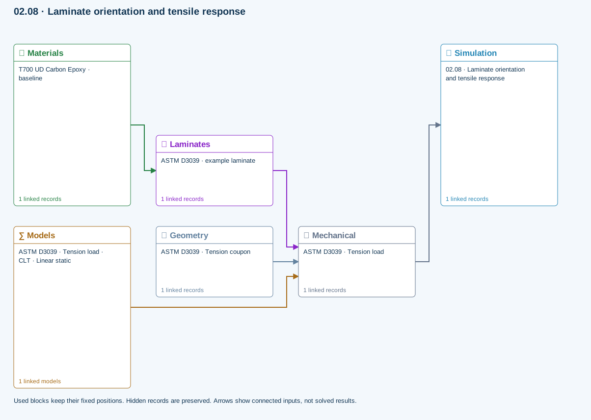
∑ Used models & submodels
Only models assigned to records used by this exercise are listed here. The full-layout option preserves the supplied starter records; no Workbench records are changed.
CLT · Linear static · ASTM D3039 · Tension load
Shared laminate stiffness drives this membrane/CLT path. Failure criteria are independent comparisons, not blended models. Fatigue is a separate assessment.
∑ Theory & assumptionsData travelling between blocks
Materials → Laminates
Stored ply stiffness, strength, density and expansion properties.
Mechanical → Simulation
SIMULATION selects this case and its analysis model; the case owns its applicable cycle and input references.
Laminates → Mechanical
Ply angles and thicknesses, stiffness, mass and ply properties.
Geometry → Mechanical
Part shape and dimensions, thickness or section definition, and model-specific geometric inputs. Each selected case consumes only the dimensions its model supports.
Models → Mechanical
Applied model assignment: CLT · Linear static. Model parameters and formulation are used by Mechanical.
Open the copied laminate and record the initial stacking sequence and total thickness.
Models: Classical laminate theory · Linear static · ASTM D3039-based
Study scope and limitations
ASTM-based teaching geometry, not certification. Grips, tabs, alignment and physical test validity are not simulated.
Micromechanics controls
Micro selects an architecture, compatible homogenization model and constituent records, then exposes composition and architecture parameters appropriate to that model. Fiber, matrix, filler and void selectors place compatible favorites first.
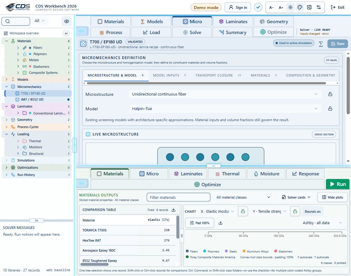
Step-by-step instructions · 5 steps
- Use the architecture/model controls together; an incompatible model is unavailable rather than silently substituted.
- Open linked constituent records with the link control. Use the selector scope menu to limit a fiber slot to fibers or browse all compatible materials when offered.
- Edit volume fractions, aspect ratio, orientation, weave, braid, crimp, void and empirical terms only when the selected model exposes them.
- Use Live view for geometry and constituent inspection; use Results for effective properties, comparisons and material creation.
- Save a composite material snapshot only after required constituent data are complete.
Laminate controls and ply-table operations
The Laminates tab manages stack source, angle, thickness, order, visibility and laminate relations. Favorite laminas and materials sort first in ply-source selectors everywhere they are used.
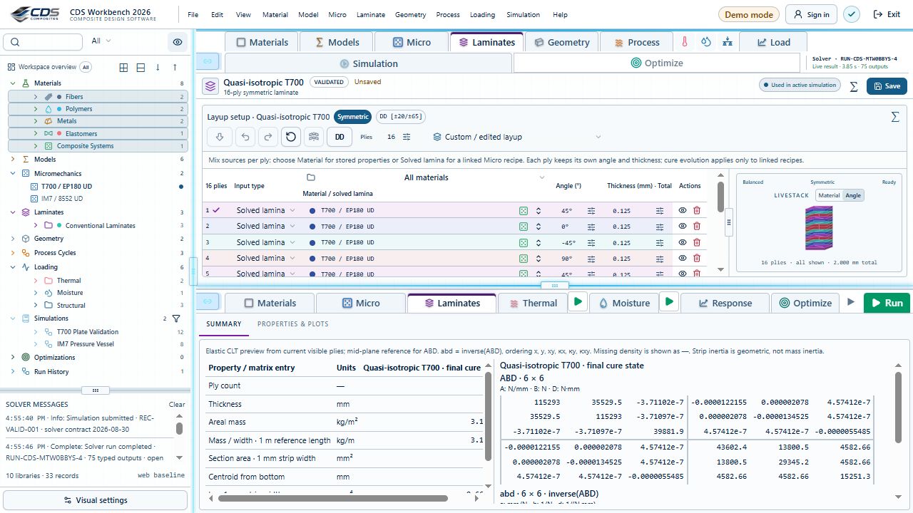
Step-by-step instructions · 5 steps
- Add, insert, duplicate, delete and reorder plies with the ply-row controls. Hidden plies are excluded from the active stack.
- Choose a stored material or Micro-derived lamina for each ply, then use the link control to open its source.
- Use row, cell and column selection before Fill, Invert, Symmetry or related bulk operations; confirm the highlighted scope.
- Apply Symmetry, Balance and Double-Double only after reviewing the proposed stack and status indicators.
- Switch LiveStack between angle and material coloring, and inspect total thickness, coupling and ABD/effective-property outputs.
Micromechanics comparison exercises
New core studies compare short-fiber orientation, porosity at fixed reinforcement, and warp fraction with weave efficiency.
Step-by-step instructions · 3 steps
- Review the prescribed architecture, volume fractions and constituent sources.
- Change one input at a time and compare E1, E2, E3, shear moduli and density.
- Save independent composite-material snapshots for comparison. Predicted stiffness does not establish measured strength or printed-part allowables.
Create a lamina
Create or duplicate a lamina record, then connect its constituent materials through the editor selectors. Material filters can limit selections to a virtual material family.
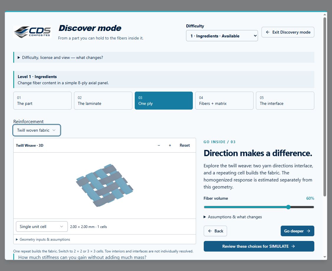
Step-by-step instructions · 4 steps
- Select the lamina type. See screenshot
- Choose constituent materials.
- Enter architecture and volume-fraction inputs.
- Review constituent references in the editor and model summary.
Organize laminate families
Create virtual folders under Laminates to group conventional, Double-Double, program-specific, or qualification laminates. The protected Conventional Laminates folder remains available as a base family.
Use the compact laminate editor
The setup inputs and laminate status are condensed above the ply table. Select each lamina, set its angle with the −90° to +90° popup slider in 5° increments, and enter a thickness greater than zero. LiveStack defaults to angle coloring; switch to material coloring when checking sources.
Apply laminate relations
Apply Symmetry, Apply Balance, and Apply DD sit with their matching status indicators above the table. Each action updates the stack toward the indicated relation and becomes disabled when the current laminate already satisfies it or already matches the predicted DD stack.
Fill from the selected cell
In the single-laminate ply table, select or right-click the source cell. The row, column and cell highlight show the target. Fill entire column from ply copies that cell’s value to every ply in that column, including rows above the source.
Step-by-step instructions · 3 steps
- Check the source ply and column named in the menu or toolbar tooltip.
- Choose Fill only after confirming that every ply should receive that value.
- Review the full sequence and save only when intended. Invert and Symmetry act on their selected column too.
Start from common layups
Use the available templates for unidirectional, cross-ply, and quasi-isotropic stacks. When compatible, the editor can propose a stiffness-matched Double-Double candidate for comparison.
Review effective properties
Lamina and laminate Results use Table, Ashby, Bar, and Line views. A single selection shows that record’s predicted property indicators. Multiple selections produce a table with properties as rows and selected laminas or laminates as columns.
Create a material from effective results
Open Create Material in a lamina or laminate result view, then choose the destination material class. The dialog proposes the source lamina or laminate name and lets you rename the new record.
Step-by-step instructions · 4 steps
- Choose the target class so its relevant property assumptions are available.
- Choose properties only or include source-identifying information.
- Leave unpredicted properties empty or fill them with the selected class assumptions, such as tension equals compression.
- Review the new material record before using it in another model.
Micromechanics controls
The Micro editor separates architecture, constituent selection, composition and model choice. Every dropdown filters the choices valid for that field; favorites remain at the top of material selectors.
Step-by-step instructions · 4 steps
- Architecture selects continuous, short-fiber, fabric, braid, particulate or another supported geometry. It controls which dimensions and model choices appear.
- Fiber, matrix, filler and void selectors link source records. The picker filter can be restricted by role; selecting All materials intentionally broadens it.
- Composition fields control constituent fractions. Resolve over-filled or negative compositions before running.
- Model selects one homogenization route. Use the adjacent theory help for equations, assumptions and required calibration rather than treating the dropdown labels as interchangeable.
Laminate editor controls
The laminate editor controls ply count, source, angle, thickness, visibility, ordering, relations and the LiveStack view. Favorites are listed first in every ply or laminate selector.
Step-by-step instructions · 5 steps
- Add or remove plies with the row controls. Reorder changes the stacking sequence and therefore coupling and bending stiffness.
- The source dropdown chooses a material or solved Micro ply. Angle sets orientation; thickness must be positive; visibility hides a ply from the current preview and should be resolved before analysis.
- Symmetry, Balance and Double-Double actions transform the current stack. Their status indicators report the stack condition; they are not solver results.
- LiveStack color mode switches between material identity and fiber angle. Rotate, zoom and section controls change inspection only.
- Right-click a cell for fill, invert or column actions. Read the highlighted source row and target scope before applying a bulk change.
Chapter review
Review the resolved properties, total thickness and stacking sequence before adding loads. Keep balance and symmetry as separate checks.
References and source sections
References are retained with the formulations they support. Software instructions describe implementation scope; a cited source does not establish independent validation of a CDS calculation.